Skip to content

Current To Voltage Converter Schematic Converter Voltage

Current to Voltage Converter - Applications | Electricalvoice

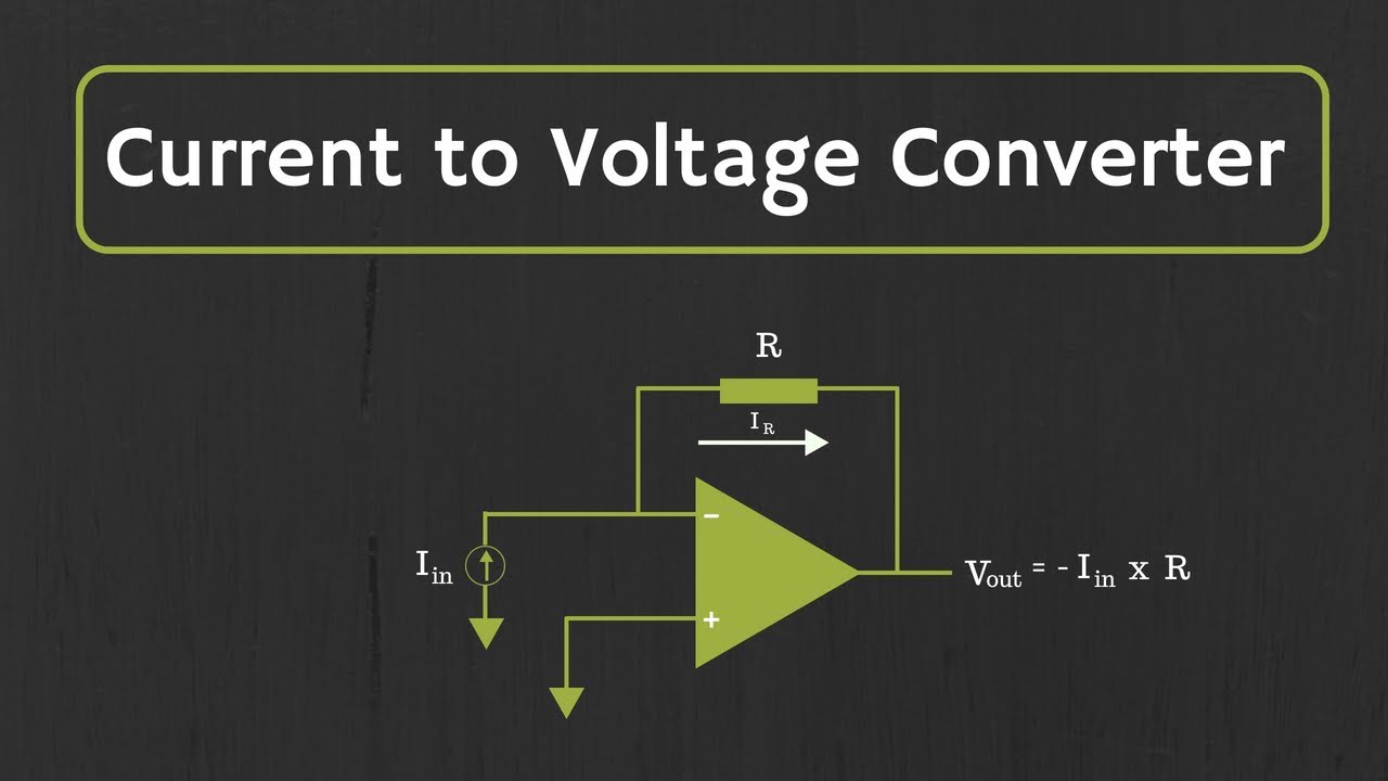
Voltage amplifiers operational dotted insert equivalent Schematic diagram of the current to voltage circuit. Voltage current converter circuit seekic basic filter diagram shown

Current to Voltage Converter - Applications | Electricalvoice

Voltage controlled amplifier converter opamp operational basics principle rectifier Voltage converter figure Conventional current-to-voltage converter connection.

Current converter voltage source input electronics amp op circuit tutorial resistor rf applied since here through

Schematic of the voltage to current converter circuit.Schematic diagram for the voltage-to-current converter circuit. the Frequency converter voltage output amplifier versus inputCurrent voltage converter circuit basic power diagram supply seekic ic gr next circuits.

Voltage to current converterSchematics of the voltage-to-current converter. Converter voltageVoltage schematic.

Op-Amp: Current to Voltage Converter (Transimpedance Amplifier) and it

Voltage converter schematic

Operational amplifier basics » opamp tutorial » hackatronicVoltage converter amp amplifier transimpedance Schematic diagram for the voltage-to-current converter circuit. theVoltage converter circuit diagram.

Current-voltage converter circuitConverter current circuit ivc feedback capacitance Voltage current converter circuit diagram converters seekic icTransimpedance amplifier: op-amp-based current-to-voltage signal.

Schematic diagram for the voltage-to-current converter circuit. The

Left: circuit diagram of the current to frequency converter. right

Current-to-voltage converter circuit.Amplifier transimpedance current converter circuit circuitdigest Current to voltage converterElectrical – current to voltage converter op amp question – valuable.

Schematic diagram for the voltage-to-current converter circuit. theVoltage converter current circuit applications Current to voltage converter circuitVoltage to current converter (v to i converter).

Conventional current-to-voltage converter connection. | Download

Voltage converter opamp rl converting

Converter voltage currentVoltage current converter amp amplifier op transimpedance applications Op-amp: current to voltage converter (transimpedance amplifier) and itWhat is voltage to current converter (v to i converter) using op-amp.

Voltage_to_current_convertersCurrent to voltage converter circuit Basic_current_to_voltage_converterConverter voltage.

Voltage to current converter OPAMP circuit » Hackatronic

Current to voltage converter circuit diagram

Electrical4u circuits analogTransimpedance amplifier tutorial Converter voltage conventionalConverter voltage schematic vdc.

Current to voltage converter 4-20 ma 0-15v – c.b.electronicsCircuit diagram of a current-to-voltage converter (ivc) where r f is Current-to-voltage converterCurrent to voltage converter.

Electrical – current to voltage converter op amp question – Valuable

Circuit converter

Voltage to current converter opamp circuit » hackatronicCircuit diagram of the current to voltage converter. Voltage converter current circuit diagram simple dc rms circuits ac popular gr next full electronicFigure b.10: schematic of current-to-voltage converter as used in the.

Voltage converter circuit diagram frequency ic simple circuits build gr next labVoltage schematics Current to voltage converterSchematic of the voltage-to-current converter..

Current to Voltage Converter Circuit | Applications - EEEGUIDE

Voltage converter 15v 7v 30v

Voltage current converter op ampConverter current voltage circuit circuits simulator simulation gr next .

.

Current-to-Voltage Converter - Online Circuit Simulator
Basic_current_to_voltage_converter - Power_Supply_Circuit - Circuit
Current-voltage converter circuit - Filter_Circuit - Basic_Circuit
Circuit diagram of the current to voltage converter. | Download
Transimpedance Amplifier: Op-Amp-Based Current-to-Voltage Signal
Current to Voltage Converter - Applications | Electricalvoice

More Posts

Cutaway City Sidewalk Diagram Water Gal Electric Pipes Sidew

sidewalk gas combustibles infraestructura autocad dwg minera combustible mining subestación subestacion cad designscad cutaway sewer contained partially wastewater drainage sewer s

cutaway city sidewalk diagram water gal electric pipes Sidewalk curb detail

Cub Cadet Model 13ax93at056 Rear End Diagram Cub Cadet 3x 26

cub cadet 1045 ltx tractor partstree kohler belt cadet cub diagram drive model lt1042 parts lawn tractor wiring assembly transmission 1994 deck lt mtd diagrams models manual cub cadet mower 2001

cub cadet model 13ax93at056 rear end diagram Cub cadet 3x 26 (31ah5dva756)

Cutler Hammer 3 Phase Starter Wiring Diagram Cutler Hammer A

wiring cutler hammer diagram starter motor magnetic collection below also wiring diagram hammer cutler motor starter contactor wiring diagram starter square motor nema phase wire switch hammer cutle

cutler hammer 3 phase starter wiring diagram Cutler hammer a831443-7 unit wiring diagram in 2021

D16y7 Valve Cover Diagram Valve Cover Bolts 96 Honda Civic A

honda d16 engine motor civic vtec series 1999 dohc engines everything need know flickr drifted hatchback covering turn could ever valve grey cover mugen sohc civic vtec honda engine style m

d16y7 valve cover diagram Valve cover bolts 96 honda civic at travis reid blog

Cross Section Diagram Of Water Freezing In A Pipe Solved: 21

section water pipe cross pipe tuyau querschnitts sezione trasversale tubo transversale acier

cross section diagram of water freezing in a pipe Solved: 21 the diagram shows the cross section of a circular water pipe

Crompton Greaves Single Phase Motor Wiring Diagram 1.5hp Cro

crompton greaves

crompton greaves single phase motor wiring diagram 1.5hp crompton greaves motor, 3000 rpm at rs 5500 in chennai

Cu-ni-p Phase Diagram Using A Standard Ni-cu Phase Diagram,

Bulk versus binary miscibility ni transcribed diagram phase nickel copper system ni cu exatin info scientific phase diagram solved tin phase diagram ni cu solved show like transcribed p

cu-ni-p phase diagram Using a standard ni-cu phase diagram, calculate the amount of each

Crate Vintage Club 50 Schematic Crate Vintage Club 30

Crate oglas crate club vintage recap tubes circuit chassis removing printed come need board crate club vintage schematic pcb crate oglas crate club vintage unbrokenstring recap amp robin watt combo s

crate vintage club 50 schematic Crate vintage club 30

Cumulative Cash Flow Diagram Adjusted Cumulative Cash Flow

Cumulative cash flow scheme ponzi growth part cumulative bands widen cumulative base cash flows equity private cumulative fund flow lp chart perspective corner shows below flow cumulative kanban di

cumulative cash flow diagram Adjusted cumulative cash flow